Friday, November 22, 2013
Home
Garage update 3
Garage update 3
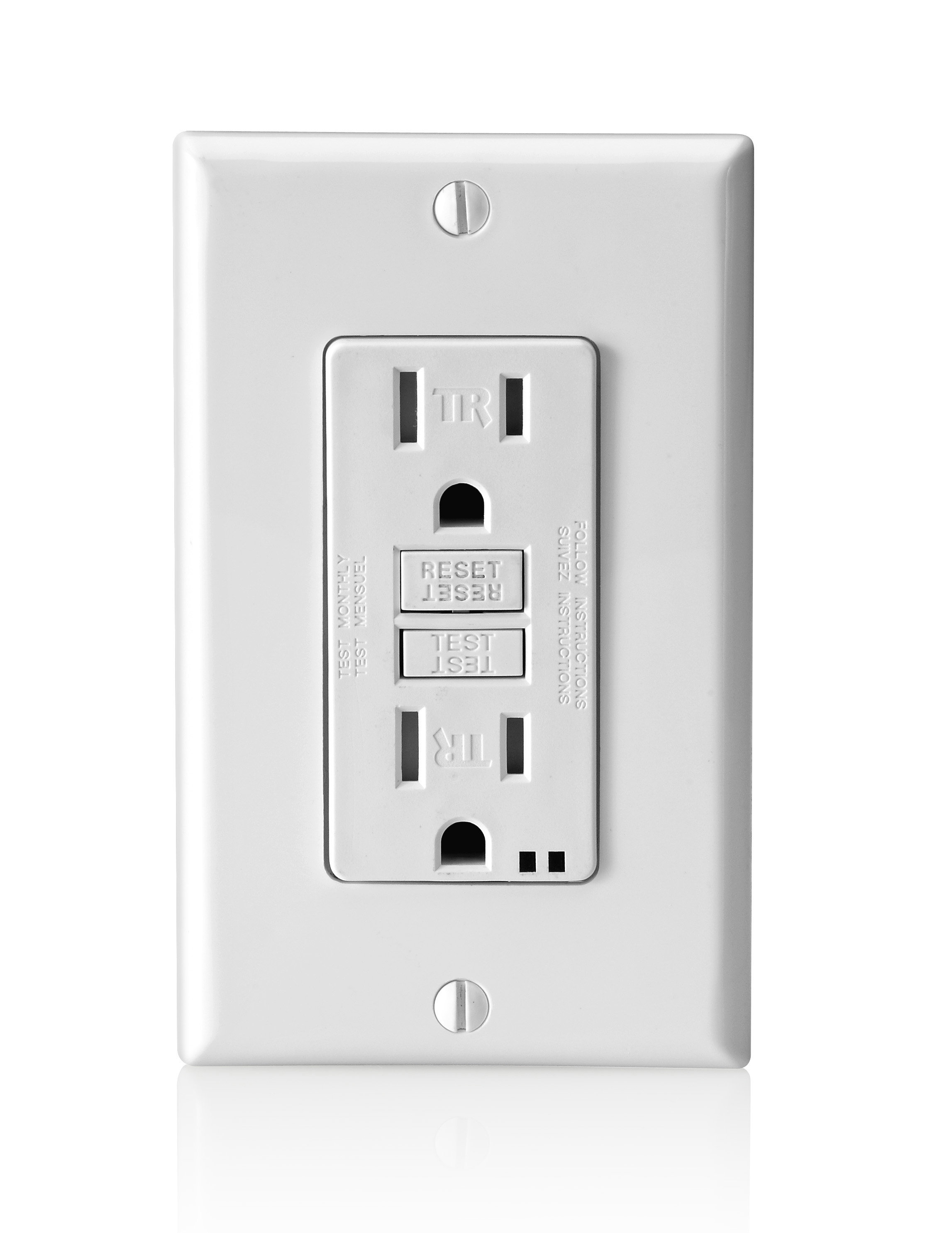
This update is mostly about the wiring in the garage. It might be a little more technical than usual, but if you are into that kinda thing, then read on.The default installation in my Rome included two 3-way light switches (one at the top of the stairs, and the other at the bottom, controlling the garage light), a light switch for the front exterior sconces, and 3 15 amp electrical outlets, for which the primary, next to the tank-less water heater, is a GFCI outlet protecting the other two. For those that don't know what GFCI is, well, it's that type of electrical outlet that has a button on it allowing you to reset, should the internal breaker get tripped, protecting you from electrical shock. They are typically installed near locations that have exposure to water. Just in case, here is what a GFCI looks like:
Looking back, I probably should have installed a 20 amp circuit, but I already bought 14-3 wire, 15 amp GFCIs, and 15 amp everything else. To even the load, I installed a separate 15 amp GFCI right next to the one already installed. I was going to install a third GFCI, making 3 dedicated circuits in the garage, but I couldn't find a 3-gang outlet box that had adjustable depth--a requirement because the box would have to telescope in and out to get to the exact depth of the diamond-plate. Here's what one of those look like:
Lowe's only had a 2-gang, so my plan was to replace it and re-install the outlet and add a second one on a dedicated circuit, that way I could connect power tools and additional lighting to the second, while the garage door opener, and tank-less water heater remain on the first.
Problem was I didn't really know the first thing about 14-3 wire, GFCI, or really anything about electrical wiring stuff. So, a big hats off to YouTube and the internet!
Before I had started, I had bought 100' of 14-3 wire. I wasn't sure how I was going to use it, but I intuitively knew that's what I needed. My logic for getting it was, well, I wanted to run additional garage outlets (two on each side of the garage, and be able to power a series of LED lights. The main thing was ensuring that the outlets would lose power if I turned off the light switch.
I also knew that I couldn't proceed any further in my diamond plate DIY project, until I knew the electrical was correct an working as I had envisioned.
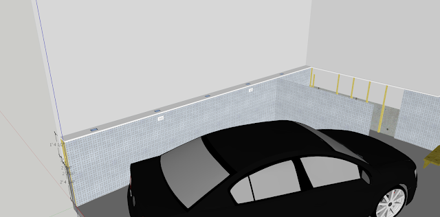
Here's a model of my vision:
The image above doesn't show the GFCI outlets, but they are on the far, left-corner wall, just to the right of the water heater (also not depicted). But you can see the two added outlets, and five LED lights flush mounted in a shelf.
Nothing ever goes well for me unless I have some idea of what I am doing, and some type of plan. So the other night, before starting on the electrical, I mocked up that plan based upon a bunch of research on the internet.
Here's what I drafted up:
This is an electrical diagram I created, that depicts the wiring in the garage. It isn't complete, in that it doesn't include the exterior wall sconces, the garage light, or light switch, but it does include the default GFCI outlet on a 15 amp circuit. My problem was how to draw all this so the lights were independent of the outlets, yet still sharing the same circuit?
The trick ended up being just as I intuitively guessed, use the 14-3 wire! You see, 14-3 wire actually has 4 wires in it. The extra wire is red, and is typically used for 3-way switches, allowing you to turn lights on/off in two locations. By joining the hot from the GFCI, to the white wire of the switch, and then connecting the extra red wire to the black wire from the switch, allowed me to separate the circuit so the outlets would remain powered when the light switch was off.
You are supposed to add some black electrical tape to the white wire when you do this to allow future electricians to realize the white is now hot. But I just used a black Sharpie and marked some dashes on the wire, kinda like what is depicted.
I am no expert on electrical codes, but I think it's necessary to install conduit if the high-voltage wire is going to be run along the exterior of the wall. So that is what I did, mostly, to protect the wire, even though it was going to be covered up anyway, with diamond plate.
In the last photo above, you can start to see where my work begins encroaching on the second major obstacle of this project--the stairs! The first obstacle was putting plate up around the tank-less water heater. I had been thinking for many days on this, like how would I cut out the stairs so that I could run the plate between it and the wall? You can see how the conduit is blocked by the stairs thus preventing me from wiring up the light switch, and getting the 14-3 wire across the wall for the second half of the garage.
At this point, it became obvious the stairs had to come down!
Taking down the stairs... that was a back-breaking effort! But fortunately they came down in two major pieces, which I should be able to paint more easily and re-install.
After that P.I.A, I continued on and started running the conduit the rest of the distance.
Once the light switch was wired up, I was getting excited!!! Was this whole plan going to work, or was it going to end in a big anti-climactic failure?
I turned back on the circuit breakers, tested and reset the GFCIs, and flipped the light switch. Wooohoooooo! It worked!
Here's me running the light and powering a drill! Yes, the drill still works after flipping the light switch off. Hurray!
With that all tested, I knew the rest of the plan would pan out, so I began installing the everything else... rinse & repeat!
And now the lights...
The lights above were just testers. Today, my 20 watt LED lights came from an Ebay purchase I made. They are much brighter, and will consumes much less energy! The pics below obviously aren't how they will look when it's done, as they will be flush mount sitting inside the shelf. But it is important to test them out. I would have ordered more watts, but it's a size thing, and the 20 watt housing dimensions were the largest I could get and still fit inside, between the wall and the plating.
Electrically a success, I moved on to business as usual, putting up more plate (but the glue is still drying, so have to wait a little more time).
Thanks for reading!
Subscribe to:
Post Comments (Atom)


0 comments:
Post a Comment